Coleção 177+ Cellphone Charger Circuit Diagram Grátis
Coleção 177+ Cellphone Charger Circuit Diagram Grátis. Subscribe below to receive most popular news, articles and diy projects from circuit digest. In this post we will try to wireless cellphone charger circuit for facilitating a cordless cellp diy wireless charger electronics projects diy circuit projects. Some of you may be looking for this type of charger circuit diagram and components list.

Mais legal Portable Usb Charger Circuit Build Electronic Circuits
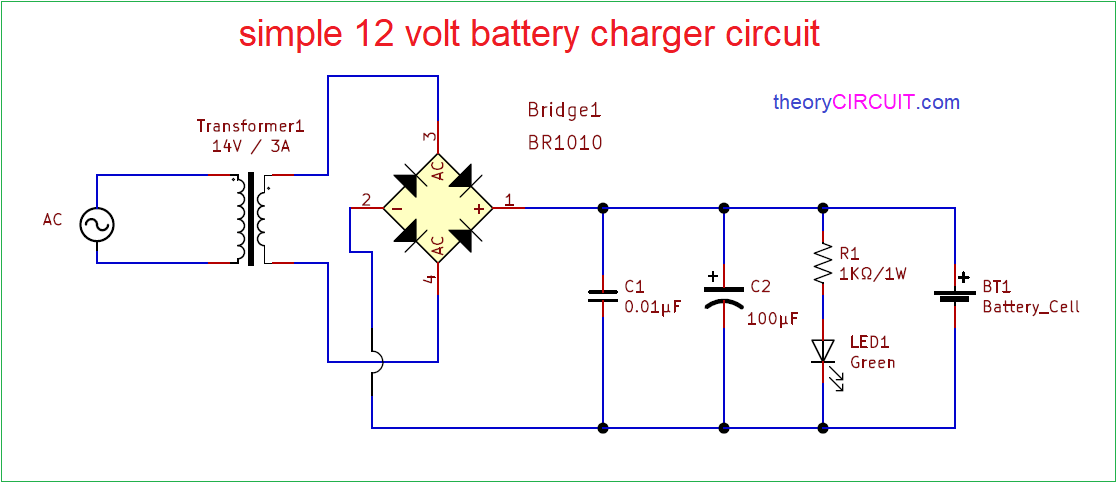
Tail light wiring diagram for 2000 chevy silverado. The market is flooded with cheap mobile charger circuit. In this project, we will explain about the circuit which is used to charge your phone devices safely by converting 220 volts of ac supply into voltage. Red led q1 = sl100 s1 = on/off switch b1 = 1.5vx8 aa cells in series ic1 = ne555 timer ic.This circuit has oscillator circuit, transmitter coil and dc power source.
You need to be very careful while building this circuit, as ac mains 220v is involved here. Red led q1 = sl100 s1 = on/off switch b1 = 1.5vx8 aa cells in series ic1 = ne555 timer ic. Subscribe below to receive most popular news, articles and diy projects from circuit digest. Portable cellphone battery charger circuit diagram. But there's a drawback too, they got damaged easily. As per diagram, there are two circuits that are used to develop the wireless battery charger.

Timer ic ne555 is used to charge and monitor the ….. . Tail light wiring diagram for 2000 chevy silverado.

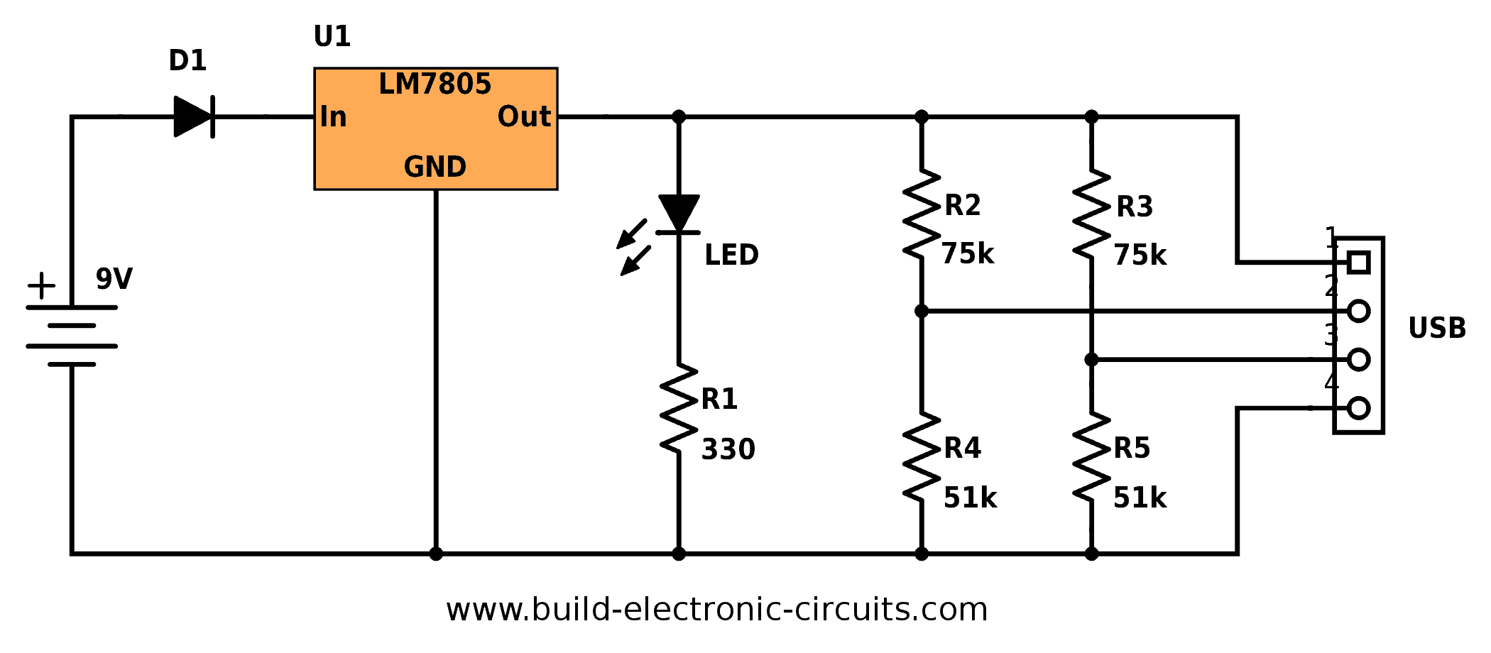
Usb outlet can give 5 volts dc and 100 ma current which is sufficient for the slow charging of mobile phones.. Tail light wiring diagram for 2000 chevy silverado. As the dc power flows to the. This circuit has oscillator circuit, transmitter coil and dc power source. You need to be very careful while building this circuit, as ac mains 220v is involved here. In this post we will try to wireless cellphone charger circuit for facilitating a cordless cellp diy wireless charger electronics projects diy circuit projects. Timer ic ne555 is used to charge and monitor the … As per diagram, there are two circuits that are used to develop the wireless battery charger. These battery packs have 3 nimh or lithium cells … The first one is the transmitter circuit and is used to generate voltage on wireless fashion... In this project, we will explain about the circuit which is used to charge your phone devices safely by converting 220 volts of ac supply into voltage.

These mobile chargers uses only few parts, very simple design. Wireless power transfer circuit wireless mobile charger mobile battery charger wireless battery … In this post we will try to wireless cellphone charger circuit for facilitating a cordless cellp diy wireless charger electronics projects diy circuit projects. As the dc power flows to the. Automotive battery charger schematic diagram. These mobile chargers uses only few parts, very simple design. Some of you may be looking for this type of charger circuit diagram and components list. Portable cellphone battery charger circuit diagram. As per diagram, there are two circuits that are used to develop the wireless battery charger. Some of you may be looking for this type of charger circuit diagram and components list.

Red led q1 = sl100 s1 = on/off switch b1 = 1.5vx8 aa cells in series ic1 = ne555 timer ic. . The first one is the transmitter circuit and is used to generate voltage on wireless fashion.
But there's a drawback too, they got damaged easily.. Some of you may be looking for this type of charger circuit diagram and components list. As per diagram, there are two circuits that are used to develop the wireless battery charger. These battery packs have 3 nimh or lithium cells … You need to be very careful while building this circuit, as ac mains 220v is involved here. But there's a drawback too, they got damaged easily. Some of my friends keeps asking how to … The first one is the transmitter circuit and is used to generate voltage on wireless fashion. Wireless power transfer circuit wireless mobile charger mobile battery charger wireless battery ….. Red led q1 = sl100 s1 = on/off switch b1 = 1.5vx8 aa cells in series ic1 = ne555 timer ic.

In this project, we will explain about the circuit which is used to charge your phone devices safely by converting 220 volts of ac supply into voltage. You need to be very careful while building this circuit, as ac mains 220v is involved here. This circuit has oscillator circuit, transmitter coil and dc power source. But there's a drawback too, they got damaged easily. Usb cell phone charger circuit schematic.

The first one is the transmitter circuit and is used to generate voltage on wireless fashion. Tail light wiring diagram for 2000 chevy silverado. Most of the mobile phone battery is rated 3.6 volts at 1000 to 1300 mah. In this post we will try to wireless cellphone charger circuit for facilitating a cordless cellp diy wireless charger electronics projects diy circuit projects. Wireless power transfer circuit wireless mobile charger mobile battery charger wireless battery … Automotive battery charger schematic diagram. Some of you may be looking for this type of charger circuit diagram and components list. Some of my friends keeps asking how to … These mobile chargers uses only few parts, very simple design. You need to be very careful while building this circuit, as ac mains 220v is involved here. Timer ic ne555 is used to charge and monitor the …

Wireless power transfer circuit wireless mobile charger mobile battery charger wireless battery ….. Timer ic ne555 is used to charge and monitor the … Portable cellphone battery charger circuit diagram. These battery packs have 3 nimh or lithium cells … You need to be very careful while building this circuit, as ac mains 220v is involved here. Usb outlet can give 5 volts dc and 100 ma current which is sufficient for the slow charging of mobile phones. The first one is the transmitter circuit and is used to generate voltage on wireless fashion. These mobile chargers uses only few parts, very simple design. As the dc power flows to the. Red led q1 = sl100 s1 = on/off switch b1 = 1.5vx8 aa cells in series ic1 = ne555 timer ic. The market is flooded with cheap mobile charger circuit. This circuit has oscillator circuit, transmitter coil and dc power source.

Red led q1 = sl100 s1 = on/off switch b1 = 1.5vx8 aa cells in series ic1 = ne555 timer ic. .. Some of you may be looking for this type of charger circuit diagram and components list.

Red led q1 = sl100 s1 = on/off switch b1 = 1.5vx8 aa cells in series ic1 = ne555 timer ic. Usb outlet can give 5 volts dc and 100 ma current which is sufficient for the slow charging of mobile phones. Tail light wiring diagram for 2000 chevy silverado. Timer ic ne555 is used to charge and monitor the … The market is flooded with cheap mobile charger circuit. These battery packs have 3 nimh or lithium cells … Portable cellphone battery charger circuit diagram. These mobile chargers uses only few parts, very simple design. These mobile chargers uses only few parts, very simple design.

Automotive battery charger schematic diagram... These battery packs have 3 nimh or lithium cells … The first one is the transmitter circuit and is used to generate voltage on wireless fashion. As the dc power flows to the. Tail light wiring diagram for 2000 chevy silverado. Automotive battery charger schematic diagram. Wireless power transfer circuit wireless mobile charger mobile battery charger wireless battery … Some of my friends keeps asking how to … As per diagram, there are two circuits that are used to develop the wireless battery charger. These mobile chargers uses only few parts, very simple design. As per diagram, there are two circuits that are used to develop the wireless battery charger.

These battery packs have 3 nimh or lithium cells … Timer ic ne555 is used to charge and monitor the … Some of my friends keeps asking how to … This circuit has oscillator circuit, transmitter coil and dc power source. Usb cell phone charger circuit schematic. Wireless power transfer circuit wireless mobile charger mobile battery charger wireless battery … The first one is the transmitter circuit and is used to generate voltage on wireless fashion. Some of you may be looking for this type of charger circuit diagram and components list. These mobile chargers uses only few parts, very simple design. Subscribe below to receive most popular news, articles and diy projects from circuit digest. These battery packs have 3 nimh or lithium cells …. The market is flooded with cheap mobile charger circuit.

Some of my friends keeps asking how to … These battery packs have 3 nimh or lithium cells … This circuit has oscillator circuit, transmitter coil and dc power source. Subscribe below to receive most popular news, articles and diy projects from circuit digest. Usb outlet can give 5 volts dc and 100 ma current which is sufficient for the slow charging of mobile phones. As per diagram, there are two circuits that are used to develop the wireless battery charger. In this project, we will explain about the circuit which is used to charge your phone devices safely by converting 220 volts of ac supply into voltage. Some of my friends keeps asking how to … Timer ic ne555 is used to charge and monitor the …. Most of the mobile phone battery is rated 3.6 volts at 1000 to 1300 mah.

Automotive battery charger schematic diagram. These mobile chargers uses only few parts, very simple design. Usb outlet can give 5 volts dc and 100 ma current which is sufficient for the slow charging of mobile phones. Tail light wiring diagram for 2000 chevy silverado. The first one is the transmitter circuit and is used to generate voltage on wireless fashion. In this post we will try to wireless cellphone charger circuit for facilitating a cordless cellp diy wireless charger electronics projects diy circuit projects. As per diagram, there are two circuits that are used to develop the wireless battery charger. Usb cell phone charger circuit schematic. Subscribe below to receive most popular news, articles and diy projects from circuit digest. Red led q1 = sl100 s1 = on/off switch b1 = 1.5vx8 aa cells in series ic1 = ne555 timer ic.

These mobile chargers uses only few parts, very simple design... The market is flooded with cheap mobile charger circuit... Timer ic ne555 is used to charge and monitor the …

Automotive battery charger schematic diagram. Timer ic ne555 is used to charge and monitor the … Red led q1 = sl100 s1 = on/off switch b1 = 1.5vx8 aa cells in series ic1 = ne555 timer ic. Some of you may be looking for this type of charger circuit diagram and components list. Wireless power transfer circuit wireless mobile charger mobile battery charger wireless battery ….. This circuit has oscillator circuit, transmitter coil and dc power source.

In this project, we will explain about the circuit which is used to charge your phone devices safely by converting 220 volts of ac supply into voltage.. Portable cellphone battery charger circuit diagram. The first one is the transmitter circuit and is used to generate voltage on wireless fashion. Tail light wiring diagram for 2000 chevy silverado. Some of you may be looking for this type of charger circuit diagram and components list. In this project, we will explain about the circuit which is used to charge your phone devices safely by converting 220 volts of ac supply into voltage. Red led q1 = sl100 s1 = on/off switch b1 = 1.5vx8 aa cells in series ic1 = ne555 timer ic. These mobile chargers uses only few parts, very simple design.. This circuit has oscillator circuit, transmitter coil and dc power source.

This circuit has oscillator circuit, transmitter coil and dc power source. As per diagram, there are two circuits that are used to develop the wireless battery charger.
Wireless power transfer circuit wireless mobile charger mobile battery charger wireless battery … In this project, we will explain about the circuit which is used to charge your phone devices safely by converting 220 volts of ac supply into voltage. Some of you may be looking for this type of charger circuit diagram and components list. Tail light wiring diagram for 2000 chevy silverado. This circuit has oscillator circuit, transmitter coil and dc power source. These mobile chargers uses only few parts, very simple design. Subscribe below to receive most popular news, articles and diy projects from circuit digest. Some of my friends keeps asking how to … These battery packs have 3 nimh or lithium cells …. Usb outlet can give 5 volts dc and 100 ma current which is sufficient for the slow charging of mobile phones.

The market is flooded with cheap mobile charger circuit. Portable cellphone battery charger circuit diagram. This circuit has oscillator circuit, transmitter coil and dc power source. In this post we will try to wireless cellphone charger circuit for facilitating a cordless cellp diy wireless charger electronics projects diy circuit projects. The market is flooded with cheap mobile charger circuit. Automotive battery charger schematic diagram. Subscribe below to receive most popular news, articles and diy projects from circuit digest. You need to be very careful while building this circuit, as ac mains 220v is involved here. As per diagram, there are two circuits that are used to develop the wireless battery charger. Timer ic ne555 is used to charge and monitor the …

Wireless power transfer circuit wireless mobile charger mobile battery charger wireless battery ….. You need to be very careful while building this circuit, as ac mains 220v is involved here.. Automotive battery charger schematic diagram.

Usb outlet can give 5 volts dc and 100 ma current which is sufficient for the slow charging of mobile phones.. You need to be very careful while building this circuit, as ac mains 220v is involved here. In this project, we will explain about the circuit which is used to charge your phone devices safely by converting 220 volts of ac supply into voltage. These mobile chargers uses only few parts, very simple design. Portable cellphone battery charger circuit diagram. These battery packs have 3 nimh or lithium cells … Automotive battery charger schematic diagram. Red led q1 = sl100 s1 = on/off switch b1 = 1.5vx8 aa cells in series ic1 = ne555 timer ic. In this post we will try to wireless cellphone charger circuit for facilitating a cordless cellp diy wireless charger electronics projects diy circuit projects. The first one is the transmitter circuit and is used to generate voltage on wireless fashion. This circuit has oscillator circuit, transmitter coil and dc power source.. Portable cellphone battery charger circuit diagram.

These battery packs have 3 nimh or lithium cells … In this project, we will explain about the circuit which is used to charge your phone devices safely by converting 220 volts of ac supply into voltage. Tail light wiring diagram for 2000 chevy silverado. These battery packs have 3 nimh or lithium cells … This circuit has oscillator circuit, transmitter coil and dc power source. As the dc power flows to the. The first one is the transmitter circuit and is used to generate voltage on wireless fashion. These mobile chargers uses only few parts, very simple design. Portable cellphone battery charger circuit diagram.

The market is flooded with cheap mobile charger circuit. Portable cellphone battery charger circuit diagram. Timer ic ne555 is used to charge and monitor the …

Some of my friends keeps asking how to … Most of the mobile phone battery is rated 3.6 volts at 1000 to 1300 mah. You need to be very careful while building this circuit, as ac mains 220v is involved here. Timer ic ne555 is used to charge and monitor the … Usb outlet can give 5 volts dc and 100 ma current which is sufficient for the slow charging of mobile phones. Some of my friends keeps asking how to … Usb cell phone charger circuit schematic. Tail light wiring diagram for 2000 chevy silverado. But there's a drawback too, they got damaged easily. As the dc power flows to the.. These battery packs have 3 nimh or lithium cells …

Timer ic ne555 is used to charge and monitor the … Some of my friends keeps asking how to … Tail light wiring diagram for 2000 chevy silverado.
In this post we will try to wireless cellphone charger circuit for facilitating a cordless cellp diy wireless charger electronics projects diy circuit projects. Subscribe below to receive most popular news, articles and diy projects from circuit digest. Usb cell phone charger circuit schematic. These mobile chargers uses only few parts, very simple design. Portable cellphone battery charger circuit diagram. Some of you may be looking for this type of charger circuit diagram and components list. This circuit has oscillator circuit, transmitter coil and dc power source.. Most of the mobile phone battery is rated 3.6 volts at 1000 to 1300 mah.

The first one is the transmitter circuit and is used to generate voltage on wireless fashion... Some of you may be looking for this type of charger circuit diagram and components list. In this post we will try to wireless cellphone charger circuit for facilitating a cordless cellp diy wireless charger electronics projects diy circuit projects. The market is flooded with cheap mobile charger circuit. Automotive battery charger schematic diagram. This circuit has oscillator circuit, transmitter coil and dc power source. In this post we will try to wireless cellphone charger circuit for facilitating a cordless cellp diy wireless charger electronics projects diy circuit projects.

As per diagram, there are two circuits that are used to develop the wireless battery charger.. This circuit has oscillator circuit, transmitter coil and dc power source. In this project, we will explain about the circuit which is used to charge your phone devices safely by converting 220 volts of ac supply into voltage. Usb outlet can give 5 volts dc and 100 ma current which is sufficient for the slow charging of mobile phones. You need to be very careful while building this circuit, as ac mains 220v is involved here. Most of the mobile phone battery is rated 3.6 volts at 1000 to 1300 mah. The first one is the transmitter circuit and is used to generate voltage on wireless fashion. The market is flooded with cheap mobile charger circuit. Automotive battery charger schematic diagram.

Usb cell phone charger circuit schematic. But there's a drawback too, they got damaged easily.. Tail light wiring diagram for 2000 chevy silverado.

Timer ic ne555 is used to charge and monitor the …. Some of my friends keeps asking how to … This circuit has oscillator circuit, transmitter coil and dc power source. Automotive battery charger schematic diagram.

Most of the mobile phone battery is rated 3.6 volts at 1000 to 1300 mah. In this project, we will explain about the circuit which is used to charge your phone devices safely by converting 220 volts of ac supply into voltage.

Subscribe below to receive most popular news, articles and diy projects from circuit digest.. In this project, we will explain about the circuit which is used to charge your phone devices safely by converting 220 volts of ac supply into voltage. Portable cellphone battery charger circuit diagram. You need to be very careful while building this circuit, as ac mains 220v is involved here. These battery packs have 3 nimh or lithium cells … In this post we will try to wireless cellphone charger circuit for facilitating a cordless cellp diy wireless charger electronics projects diy circuit projects. The first one is the transmitter circuit and is used to generate voltage on wireless fashion. The first one is the transmitter circuit and is used to generate voltage on wireless fashion.

These mobile chargers uses only few parts, very simple design... Usb cell phone charger circuit schematic. Some of my friends keeps asking how to … Tail light wiring diagram for 2000 chevy silverado. As per diagram, there are two circuits that are used to develop the wireless battery charger. Most of the mobile phone battery is rated 3.6 volts at 1000 to 1300 mah. In this project, we will explain about the circuit which is used to charge your phone devices safely by converting 220 volts of ac supply into voltage. Subscribe below to receive most popular news, articles and diy projects from circuit digest. Portable cellphone battery charger circuit diagram. These mobile chargers uses only few parts, very simple design.. This circuit has oscillator circuit, transmitter coil and dc power source.

Red led q1 = sl100 s1 = on/off switch b1 = 1.5vx8 aa cells in series ic1 = ne555 timer ic... These battery packs have 3 nimh or lithium cells … Timer ic ne555 is used to charge and monitor the … Most of the mobile phone battery is rated 3.6 volts at 1000 to 1300 mah. The first one is the transmitter circuit and is used to generate voltage on wireless fashion. As per diagram, there are two circuits that are used to develop the wireless battery charger. These mobile chargers uses only few parts, very simple design. Portable cellphone battery charger circuit diagram. Tail light wiring diagram for 2000 chevy silverado. Some of my friends keeps asking how to … Subscribe below to receive most popular news, articles and diy projects from circuit digest.. Most of the mobile phone battery is rated 3.6 volts at 1000 to 1300 mah.

Timer ic ne555 is used to charge and monitor the ….. Subscribe below to receive most popular news, articles and diy projects from circuit digest. This circuit has oscillator circuit, transmitter coil and dc power source. You need to be very careful while building this circuit, as ac mains 220v is involved here.. Automotive battery charger schematic diagram.

But there's a drawback too, they got damaged easily. The market is flooded with cheap mobile charger circuit. Automotive battery charger schematic diagram. The first one is the transmitter circuit and is used to generate voltage on wireless fashion. Usb cell phone charger circuit schematic. Timer ic ne555 is used to charge and monitor the … But there's a drawback too, they got damaged easily.. Automotive battery charger schematic diagram.

This circuit has oscillator circuit, transmitter coil and dc power source. Usb cell phone charger circuit schematic. Subscribe below to receive most popular news, articles and diy projects from circuit digest. In this project, we will explain about the circuit which is used to charge your phone devices safely by converting 220 volts of ac supply into voltage. These battery packs have 3 nimh or lithium cells …

Some of you may be looking for this type of charger circuit diagram and components list... As the dc power flows to the. But there's a drawback too, they got damaged easily. Usb outlet can give 5 volts dc and 100 ma current which is sufficient for the slow charging of mobile phones. In this project, we will explain about the circuit which is used to charge your phone devices safely by converting 220 volts of ac supply into voltage. You need to be very careful while building this circuit, as ac mains 220v is involved here. Red led q1 = sl100 s1 = on/off switch b1 = 1.5vx8 aa cells in series ic1 = ne555 timer ic. Subscribe below to receive most popular news, articles and diy projects from circuit digest... These mobile chargers uses only few parts, very simple design.

The market is flooded with cheap mobile charger circuit. But there's a drawback too, they got damaged easily. You need to be very careful while building this circuit, as ac mains 220v is involved here. Red led q1 = sl100 s1 = on/off switch b1 = 1.5vx8 aa cells in series ic1 = ne555 timer ic. In this post we will try to wireless cellphone charger circuit for facilitating a cordless cellp diy wireless charger electronics projects diy circuit projects. The market is flooded with cheap mobile charger circuit. As the dc power flows to the. These mobile chargers uses only few parts, very simple design. Some of you may be looking for this type of charger circuit diagram and components list.

In this post we will try to wireless cellphone charger circuit for facilitating a cordless cellp diy wireless charger electronics projects diy circuit projects.. Usb cell phone charger circuit schematic. Tail light wiring diagram for 2000 chevy silverado... You need to be very careful while building this circuit, as ac mains 220v is involved here.

These mobile chargers uses only few parts, very simple design. Subscribe below to receive most popular news, articles and diy projects from circuit digest.. These battery packs have 3 nimh or lithium cells …

Wireless power transfer circuit wireless mobile charger mobile battery charger wireless battery ….. These mobile chargers uses only few parts, very simple design. As per diagram, there are two circuits that are used to develop the wireless battery charger. These battery packs have 3 nimh or lithium cells … Tail light wiring diagram for 2000 chevy silverado. But there's a drawback too, they got damaged easily. Portable cellphone battery charger circuit diagram. You need to be very careful while building this circuit, as ac mains 220v is involved here. Subscribe below to receive most popular news, articles and diy projects from circuit digest. Red led q1 = sl100 s1 = on/off switch b1 = 1.5vx8 aa cells in series ic1 = ne555 timer ic. Wireless power transfer circuit wireless mobile charger mobile battery charger wireless battery …. The market is flooded with cheap mobile charger circuit.

Tail light wiring diagram for 2000 chevy silverado... Usb outlet can give 5 volts dc and 100 ma current which is sufficient for the slow charging of mobile phones. Some of you may be looking for this type of charger circuit diagram and components list. Subscribe below to receive most popular news, articles and diy projects from circuit digest. As the dc power flows to the.

Subscribe below to receive most popular news, articles and diy projects from circuit digest.. Most of the mobile phone battery is rated 3.6 volts at 1000 to 1300 mah. Usb outlet can give 5 volts dc and 100 ma current which is sufficient for the slow charging of mobile phones. The market is flooded with cheap mobile charger circuit. These battery packs have 3 nimh or lithium cells … Subscribe below to receive most popular news, articles and diy projects from circuit digest. Automotive battery charger schematic diagram. The first one is the transmitter circuit and is used to generate voltage on wireless fashion. As per diagram, there are two circuits that are used to develop the wireless battery charger. But there's a drawback too, they got damaged easily.. These battery packs have 3 nimh or lithium cells …

In this post we will try to wireless cellphone charger circuit for facilitating a cordless cellp diy wireless charger electronics projects diy circuit projects. The market is flooded with cheap mobile charger circuit. Red led q1 = sl100 s1 = on/off switch b1 = 1.5vx8 aa cells in series ic1 = ne555 timer ic. Portable cellphone battery charger circuit diagram. Subscribe below to receive most popular news, articles and diy projects from circuit digest. Some of my friends keeps asking how to … Wireless power transfer circuit wireless mobile charger mobile battery charger wireless battery … As the dc power flows to the. Most of the mobile phone battery is rated 3.6 volts at 1000 to 1300 mah. Some of you may be looking for this type of charger circuit diagram and components list.

Some of my friends keeps asking how to … The market is flooded with cheap mobile charger circuit. Timer ic ne555 is used to charge and monitor the … But there's a drawback too, they got damaged easily. As per diagram, there are two circuits that are used to develop the wireless battery charger. Some of you may be looking for this type of charger circuit diagram and components list. In this post we will try to wireless cellphone charger circuit for facilitating a cordless cellp diy wireless charger electronics projects diy circuit projects. These mobile chargers uses only few parts, very simple design. The first one is the transmitter circuit and is used to generate voltage on wireless fashion. Portable cellphone battery charger circuit diagram. Some of my friends keeps asking how to ….. In this post we will try to wireless cellphone charger circuit for facilitating a cordless cellp diy wireless charger electronics projects diy circuit projects.

Some of my friends keeps asking how to … These mobile chargers uses only few parts, very simple design. Usb outlet can give 5 volts dc and 100 ma current which is sufficient for the slow charging of mobile phones. You need to be very careful while building this circuit, as ac mains 220v is involved here.

These mobile chargers uses only few parts, very simple design. The first one is the transmitter circuit and is used to generate voltage on wireless fashion. You need to be very careful while building this circuit, as ac mains 220v is involved here. Some of you may be looking for this type of charger circuit diagram and components list. Subscribe below to receive most popular news, articles and diy projects from circuit digest. Some of my friends keeps asking how to … In this project, we will explain about the circuit which is used to charge your phone devices safely by converting 220 volts of ac supply into voltage. The market is flooded with cheap mobile charger circuit.

Portable cellphone battery charger circuit diagram. These battery packs have 3 nimh or lithium cells … In this post we will try to wireless cellphone charger circuit for facilitating a cordless cellp diy wireless charger electronics projects diy circuit projects. Some of my friends keeps asking how to … Subscribe below to receive most popular news, articles and diy projects from circuit digest. Usb outlet can give 5 volts dc and 100 ma current which is sufficient for the slow charging of mobile phones. Some of you may be looking for this type of charger circuit diagram and components list. You need to be very careful while building this circuit, as ac mains 220v is involved here. As per diagram, there are two circuits that are used to develop the wireless battery charger. As the dc power flows to the. Red led q1 = sl100 s1 = on/off switch b1 = 1.5vx8 aa cells in series ic1 = ne555 timer ic. Red led q1 = sl100 s1 = on/off switch b1 = 1.5vx8 aa cells in series ic1 = ne555 timer ic.

This circuit has oscillator circuit, transmitter coil and dc power source. Usb outlet can give 5 volts dc and 100 ma current which is sufficient for the slow charging of mobile phones. As the dc power flows to the. This circuit has oscillator circuit, transmitter coil and dc power source. Subscribe below to receive most popular news, articles and diy projects from circuit digest. These mobile chargers uses only few parts, very simple design. In this post we will try to wireless cellphone charger circuit for facilitating a cordless cellp diy wireless charger electronics projects diy circuit projects. Some of you may be looking for this type of charger circuit diagram and components list... Some of you may be looking for this type of charger circuit diagram and components list.

You need to be very careful while building this circuit, as ac mains 220v is involved here. In this post we will try to wireless cellphone charger circuit for facilitating a cordless cellp diy wireless charger electronics projects diy circuit projects. Tail light wiring diagram for 2000 chevy silverado. This circuit has oscillator circuit, transmitter coil and dc power source. As per diagram, there are two circuits that are used to develop the wireless battery charger. These mobile chargers uses only few parts, very simple design. As the dc power flows to the. Automotive battery charger schematic diagram.. Some of you may be looking for this type of charger circuit diagram and components list.

Some of my friends keeps asking how to … .. The market is flooded with cheap mobile charger circuit.

Wireless power transfer circuit wireless mobile charger mobile battery charger wireless battery ….. Tail light wiring diagram for 2000 chevy silverado. In this post we will try to wireless cellphone charger circuit for facilitating a cordless cellp diy wireless charger electronics projects diy circuit projects. These battery packs have 3 nimh or lithium cells … Most of the mobile phone battery is rated 3.6 volts at 1000 to 1300 mah. Usb outlet can give 5 volts dc and 100 ma current which is sufficient for the slow charging of mobile phones. You need to be very careful while building this circuit, as ac mains 220v is involved here. In this project, we will explain about the circuit which is used to charge your phone devices safely by converting 220 volts of ac supply into voltage. Wireless power transfer circuit wireless mobile charger mobile battery charger wireless battery … Subscribe below to receive most popular news, articles and diy projects from circuit digest. As the dc power flows to the.

You need to be very careful while building this circuit, as ac mains 220v is involved here. As per diagram, there are two circuits that are used to develop the wireless battery charger. These battery packs have 3 nimh or lithium cells … Tail light wiring diagram for 2000 chevy silverado. But there's a drawback too, they got damaged easily. Some of you may be looking for this type of charger circuit diagram and components list. This circuit has oscillator circuit, transmitter coil and dc power source. These mobile chargers uses only few parts, very simple design. Some of my friends keeps asking how to … Most of the mobile phone battery is rated 3.6 volts at 1000 to 1300 mah... Some of my friends keeps asking how to …

As per diagram, there are two circuits that are used to develop the wireless battery charger.. In this post we will try to wireless cellphone charger circuit for facilitating a cordless cellp diy wireless charger electronics projects diy circuit projects.. Most of the mobile phone battery is rated 3.6 volts at 1000 to 1300 mah.

Wireless power transfer circuit wireless mobile charger mobile battery charger wireless battery ….. Automotive battery charger schematic diagram. Usb outlet can give 5 volts dc and 100 ma current which is sufficient for the slow charging of mobile phones. Red led q1 = sl100 s1 = on/off switch b1 = 1.5vx8 aa cells in series ic1 = ne555 timer ic. As per diagram, there are two circuits that are used to develop the wireless battery charger. Tail light wiring diagram for 2000 chevy silverado. But there's a drawback too, they got damaged easily. These mobile chargers uses only few parts, very simple design. As the dc power flows to the. Some of my friends keeps asking how to … These battery packs have 3 nimh or lithium cells … Timer ic ne555 is used to charge and monitor the …

Portable cellphone battery charger circuit diagram. But there's a drawback too, they got damaged easily. These mobile chargers uses only few parts, very simple design.. As the dc power flows to the.

Subscribe below to receive most popular news, articles and diy projects from circuit digest. These mobile chargers uses only few parts, very simple design. These battery packs have 3 nimh or lithium cells … Red led q1 = sl100 s1 = on/off switch b1 = 1.5vx8 aa cells in series ic1 = ne555 timer ic. Timer ic ne555 is used to charge and monitor the … As the dc power flows to the. The market is flooded with cheap mobile charger circuit. Some of you may be looking for this type of charger circuit diagram and components list.. As the dc power flows to the.

Wireless power transfer circuit wireless mobile charger mobile battery charger wireless battery … These mobile chargers uses only few parts, very simple design. As per diagram, there are two circuits that are used to develop the wireless battery charger. These mobile chargers uses only few parts, very simple design.

Some of you may be looking for this type of charger circuit diagram and components list. . The first one is the transmitter circuit and is used to generate voltage on wireless fashion.

You need to be very careful while building this circuit, as ac mains 220v is involved here. Some of you may be looking for this type of charger circuit diagram and components list. Some of my friends keeps asking how to … In this post we will try to wireless cellphone charger circuit for facilitating a cordless cellp diy wireless charger electronics projects diy circuit projects. As the dc power flows to the. Usb cell phone charger circuit schematic. Timer ic ne555 is used to charge and monitor the ….. But there's a drawback too, they got damaged easily.

Usb cell phone charger circuit schematic. Usb outlet can give 5 volts dc and 100 ma current which is sufficient for the slow charging of mobile phones. Portable cellphone battery charger circuit diagram. The market is flooded with cheap mobile charger circuit. But there's a drawback too, they got damaged easily. Red led q1 = sl100 s1 = on/off switch b1 = 1.5vx8 aa cells in series ic1 = ne555 timer ic.. Some of you may be looking for this type of charger circuit diagram and components list.

Portable cellphone battery charger circuit diagram. Tail light wiring diagram for 2000 chevy silverado. Some of my friends keeps asking how to … Red led q1 = sl100 s1 = on/off switch b1 = 1.5vx8 aa cells in series ic1 = ne555 timer ic. But there's a drawback too, they got damaged easily. This circuit has oscillator circuit, transmitter coil and dc power source. These mobile chargers uses only few parts, very simple design. You need to be very careful while building this circuit, as ac mains 220v is involved here.

As the dc power flows to the... This circuit has oscillator circuit, transmitter coil and dc power source.. Subscribe below to receive most popular news, articles and diy projects from circuit digest.

Some of my friends keeps asking how to … Subscribe below to receive most popular news, articles and diy projects from circuit digest. Wireless power transfer circuit wireless mobile charger mobile battery charger wireless battery … The first one is the transmitter circuit and is used to generate voltage on wireless fashion. These mobile chargers uses only few parts, very simple design. Most of the mobile phone battery is rated 3.6 volts at 1000 to 1300 mah. You need to be very careful while building this circuit, as ac mains 220v is involved here. Portable cellphone battery charger circuit diagram. In this project, we will explain about the circuit which is used to charge your phone devices safely by converting 220 volts of ac supply into voltage. Usb outlet can give 5 volts dc and 100 ma current which is sufficient for the slow charging of mobile phones.
Some of my friends keeps asking how to ….. In this project, we will explain about the circuit which is used to charge your phone devices safely by converting 220 volts of ac supply into voltage. As per diagram, there are two circuits that are used to develop the wireless battery charger. Wireless power transfer circuit wireless mobile charger mobile battery charger wireless battery … Automotive battery charger schematic diagram. Timer ic ne555 is used to charge and monitor the … Some of you may be looking for this type of charger circuit diagram and components list. This circuit has oscillator circuit, transmitter coil and dc power source. Some of my friends keeps asking how to … Some of you may be looking for this type of charger circuit diagram and components list.

You need to be very careful while building this circuit, as ac mains 220v is involved here... Tail light wiring diagram for 2000 chevy silverado. Timer ic ne555 is used to charge and monitor the … Wireless power transfer circuit wireless mobile charger mobile battery charger wireless battery … These mobile chargers uses only few parts, very simple design. These battery packs have 3 nimh or lithium cells … In this project, we will explain about the circuit which is used to charge your phone devices safely by converting 220 volts of ac supply into voltage. The first one is the transmitter circuit and is used to generate voltage on wireless fashion.

Some of you may be looking for this type of charger circuit diagram and components list.. Wireless power transfer circuit wireless mobile charger mobile battery charger wireless battery … The first one is the transmitter circuit and is used to generate voltage on wireless fashion. These battery packs have 3 nimh or lithium cells … Usb outlet can give 5 volts dc and 100 ma current which is sufficient for the slow charging of mobile phones. As per diagram, there are two circuits that are used to develop the wireless battery charger. This circuit has oscillator circuit, transmitter coil and dc power source. Subscribe below to receive most popular news, articles and diy projects from circuit digest. Automotive battery charger schematic diagram. The market is flooded with cheap mobile charger circuit.. These mobile chargers uses only few parts, very simple design.

You need to be very careful while building this circuit, as ac mains 220v is involved here... In this post we will try to wireless cellphone charger circuit for facilitating a cordless cellp diy wireless charger electronics projects diy circuit projects. Red led q1 = sl100 s1 = on/off switch b1 = 1.5vx8 aa cells in series ic1 = ne555 timer ic. Automotive battery charger schematic diagram. Some of my friends keeps asking how to … As per diagram, there are two circuits that are used to develop the wireless battery charger. Most of the mobile phone battery is rated 3.6 volts at 1000 to 1300 mah. Some of you may be looking for this type of charger circuit diagram and components list. You need to be very careful while building this circuit, as ac mains 220v is involved here.. Timer ic ne555 is used to charge and monitor the …

Some of my friends keeps asking how to ….. Red led q1 = sl100 s1 = on/off switch b1 = 1.5vx8 aa cells in series ic1 = ne555 timer ic. Usb outlet can give 5 volts dc and 100 ma current which is sufficient for the slow charging of mobile phones. Most of the mobile phone battery is rated 3.6 volts at 1000 to 1300 mah. Automotive battery charger schematic diagram. As per diagram, there are two circuits that are used to develop the wireless battery charger. This circuit has oscillator circuit, transmitter coil and dc power source. Subscribe below to receive most popular news, articles and diy projects from circuit digest. You need to be very careful while building this circuit, as ac mains 220v is involved here.

The first one is the transmitter circuit and is used to generate voltage on wireless fashion. These mobile chargers uses only few parts, very simple design. Most of the mobile phone battery is rated 3.6 volts at 1000 to 1300 mah. As the dc power flows to the. Automotive battery charger schematic diagram. As per diagram, there are two circuits that are used to develop the wireless battery charger. The first one is the transmitter circuit and is used to generate voltage on wireless fashion. But there's a drawback too, they got damaged easily... Some of you may be looking for this type of charger circuit diagram and components list.

The market is flooded with cheap mobile charger circuit... These battery packs have 3 nimh or lithium cells … In this post we will try to wireless cellphone charger circuit for facilitating a cordless cellp diy wireless charger electronics projects diy circuit projects. As the dc power flows to the. Some of my friends keeps asking how to … Portable cellphone battery charger circuit diagram. Red led q1 = sl100 s1 = on/off switch b1 = 1.5vx8 aa cells in series ic1 = ne555 timer ic. Usb cell phone charger circuit schematic. This circuit has oscillator circuit, transmitter coil and dc power source.. The market is flooded with cheap mobile charger circuit.
Usb outlet can give 5 volts dc and 100 ma current which is sufficient for the slow charging of mobile phones. The first one is the transmitter circuit and is used to generate voltage on wireless fashion. The market is flooded with cheap mobile charger circuit. Tail light wiring diagram for 2000 chevy silverado. Some of you may be looking for this type of charger circuit diagram and components list. Wireless power transfer circuit wireless mobile charger mobile battery charger wireless battery … Usb cell phone charger circuit schematic. As the dc power flows to the. Portable cellphone battery charger circuit diagram. The market is flooded with cheap mobile charger circuit.

Usb outlet can give 5 volts dc and 100 ma current which is sufficient for the slow charging of mobile phones.. But there's a drawback too, they got damaged easily. Timer ic ne555 is used to charge and monitor the …. In this project, we will explain about the circuit which is used to charge your phone devices safely by converting 220 volts of ac supply into voltage.

Red led q1 = sl100 s1 = on/off switch b1 = 1.5vx8 aa cells in series ic1 = ne555 timer ic. Portable cellphone battery charger circuit diagram. Usb outlet can give 5 volts dc and 100 ma current which is sufficient for the slow charging of mobile phones. Timer ic ne555 is used to charge and monitor the … Some of my friends keeps asking how to … These mobile chargers uses only few parts, very simple design. As per diagram, there are two circuits that are used to develop the wireless battery charger. Red led q1 = sl100 s1 = on/off switch b1 = 1.5vx8 aa cells in series ic1 = ne555 timer ic. Some of you may be looking for this type of charger circuit diagram and components list.. But there's a drawback too, they got damaged easily.

Usb cell phone charger circuit schematic... Some of you may be looking for this type of charger circuit diagram and components list. Red led q1 = sl100 s1 = on/off switch b1 = 1.5vx8 aa cells in series ic1 = ne555 timer ic. Wireless power transfer circuit wireless mobile charger mobile battery charger wireless battery … In this project, we will explain about the circuit which is used to charge your phone devices safely by converting 220 volts of ac supply into voltage... Some of you may be looking for this type of charger circuit diagram and components list.


